For grooving and parting stability, start with groove width and depth, workpiece diameter, external or internal direction, holder and blade codes, overhang, material and the observed failure mode. KENFA can route the inquiry to grooving inserts, blades and holders, while exact fit, grade, coating, chipbreaker and cutting conditions remain model- and setup-specific.
Which dimensions define a grooving or parting request?
| Buyer input | What to send | Compatibility boundary |
|---|---|---|
| Operation | External groove, internal groove, face groove, parting or form groove | Operation and direction narrow the holder and insert route. |
| Feature geometry | Width, depth, diameter, corner or profile and required bottom condition | Width alone does not confirm blade, insert or reach. |
| Assembly | Full holder, blade and insert codes plus hand and orientation | Seat, clamp and direction must agree across the assembly. |
| Setup | Overhang, machine type, clamping, coolant and available clearance | Support and access affect stability. |
| Observed issue | Vibration, breakage, chip packing, burr, poor finish or size error | The failure mode identifies the information that needs review. |
Which product families should buyers compare?
- Grooving Inserts & Blades for insert, blade and custom-profile routes.
- Grooving Tool Holders for holder, blade support and machine orientation.
- Cutting Inserts when the current insert designation is the strongest reference.
Which catalog images help identify the family?
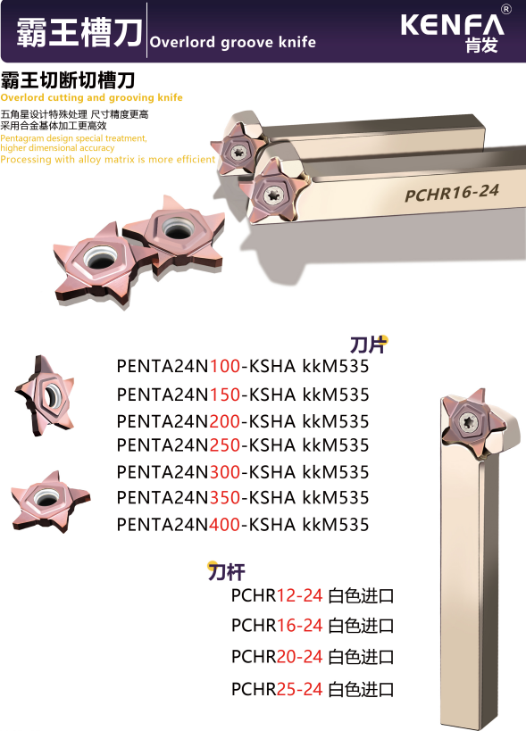
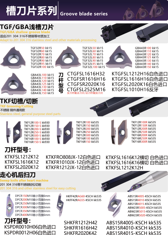
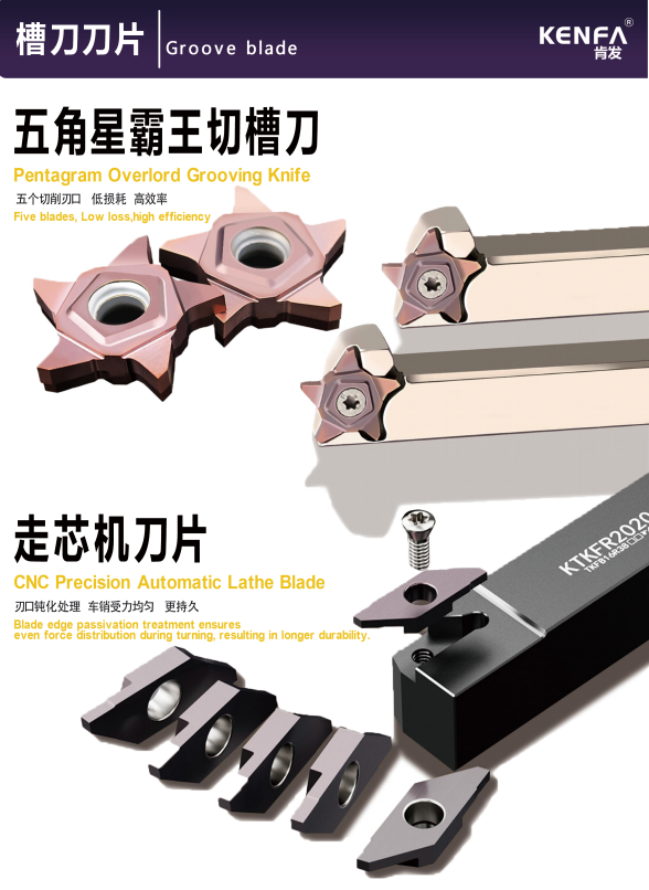
These images show several grooving families and holder routes. Confirm the exact blade, insert and holder codes before treating any visible series as compatible.
How should stability problems be reported?
| Problem | Checks to report | Useful attachment |
|---|---|---|
| Vibration or blade breakage | Overhang, support, cut-off diameter, depth, clamping and machine orientation | Setup photo and broken-edge photo |
| Poor chip evacuation | Internal or external use, groove depth, coolant access and chip form | Chip photo and feature drawing |
| Wrong width or profile | Controlled dimensions, corner form and current model codes | Dimensioned profile drawing |
| Orientation mismatch | Hand, feed direction, spindle direction and holder position | Machine-side setup photo |
What should buyers send through RFQ?
Use the grooving RFQ path with the full assembly codes and feature drawing. Review How to Prepare a Cutting Tool Compatibility RFQ, How to Choose Carbide Inserts and Catalogs & Technical Resources before submitting.
Buyer Questions
Is groove width enough to identify a replacement?
No. Depth, direction, holder, blade or insert code, profile and machine setup are also required.
Why should both blade and holder codes be sent?
The blade or insert and its support system form a compatibility chain; one code does not prove the other interface.
Can a family image confirm the chipbreaker or coating?
No. Those fields must be bound to the exact selected model and application.
What helps KENFA review repeated breakage?
Send setup and edge photos with overhang, clamping, material, operation and current cutting-condition context.
Source Notes
KENFA catalog images CI-22, CI-25 and CI-72 show grooving product-family routes. They do not establish holder fit, coating, cutting conditions, tool life, stock or delivery. Last reviewed July 12, 2026.